Acoustic panels play a crucial role in controlling:
- Echo
- Reverberation
- Background noise
- Speech clarity
Poor-quality panels may only provide minimal improvement, while high-end panels can significantly enhance both sound quality and overall environment comfort.
1. Material Quality and Composition
Cheap Acoustic Panels
Low-cost panels are often made from:
- Low-density foam
- Inferior fiber materials
- Thin or inconsistent cores
These materials may degrade quickly and offer limited sound absorption, especially at certain frequencies.
High-End Acoustic Panels
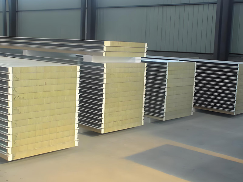
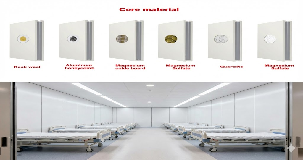
Premium panels use carefully selected materials such as:
- High-density polyester fiber
- Mineral wool or engineered acoustic cores
- High-quality MDF and wood veneers (for wood slat panels)
These materials are designed to deliver consistent and effective sound absorption across a wide frequency range.
👉 Key Difference: Higher density and better material composition result in superior acoustic performance.
2. Acoustic Performance and Testing
Cheap Panels
Many low-cost panels are not professionally tested, meaning:
- No verified acoustic ratings (like NRC)
- Inconsistent performance
- Limited effectiveness in real environments
High-End Panels
Premium acoustic panels are:
- Engineered for specific acoustic performance
- Tested under standardized conditions
- Designed to optimize sound absorption
They provide reliable results in both residential and commercial applications.
👉 Key Difference: High-end panels offer proven, measurable acoustic performance.
3. Design and Aesthetic Appeal
Cheap Panels
Budget panels often focus only on function, resulting in:
- Basic or outdated designs
- Limited color and finish options
- Industrial or unattractive appearance
High-End Panels
Modern high-end panels, especially wood slat acoustic panels, are designed as architectural features.
They offer:
- Natural wood finishes
- Clean, modern lines
- Customizable styles
- Seamless integration into interior design
👉 Key Difference: Premium panels enhance both acoustics and visual design.
4. Durability and Lifespan
Cheap Panels
Low-quality panels may:
- Lose shape over time
- Sag or deform
- Fade or wear quickly
- Be sensitive to moisture
High-End Panels
High-end products are built for longevity, featuring:
- Stable structural design
- Durable surface finishes
- Resistance to wear and environmental factors
👉 Key Difference: Premium panels provide long-term reliability and performance.
5. Fire Safety and Environmental Standards
Cheap Panels
Many low-cost panels do not meet safety standards, which can pose risks in:
- Commercial buildings
- Public spaces
- Hospitality environments
High-End Panels
Professional acoustic panels are often:
- Fire-resistant
- Low-emission (eco-friendly)
- Certified according to international standards
👉 Key Difference: High-end panels ensure safety, compliance, and sustainability.
6. Installation and Precision Manufacturing
Cheap Panels
Budget options may suffer from:
- Inconsistent dimensions
- Poor edge finishing
- Difficult installation
High-End Panels
Premium panels are manufactured with precision, offering:
- Accurate sizing
- Easy installation systems
- Clean joints and alignment
👉 Key Difference: Better manufacturing leads to faster installation and a more professional finish.
7. Overall Value vs Initial Cost
While cheap acoustic panels may seem cost-effective upfront, they often require:
- Replacement over time
- Additional panels to achieve desired results
- Compromises in design and performance
High-end acoustic panels, although more expensive initially, provide:
- Better performance
- Longer lifespan
- Higher aesthetic value
- Greater return on investment
👉 Key Difference: Premium panels deliver better long-term value.
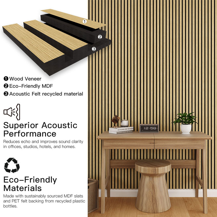
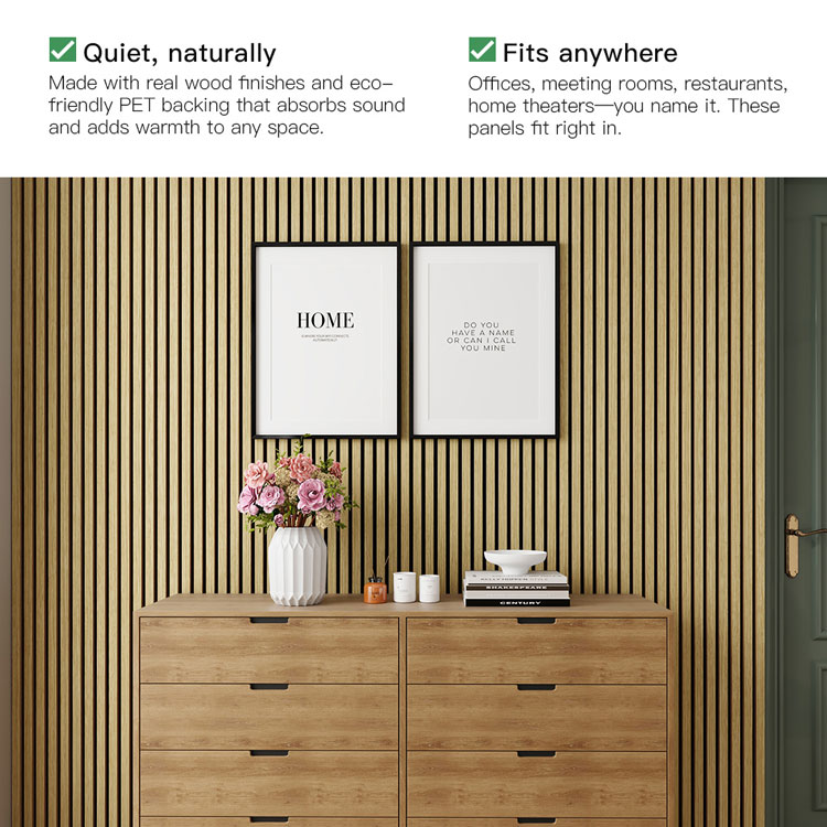
Why Wood Slat Acoustic Panels Represent High-End Solutions
Among premium options, wood slat acoustic panels stand out as a top-tier solution.
Their structure typically includes:
- Decorative wood slats
- Acoustic felt backing
- Engineered spacing for optimized sound absorption
They combine:
- High-performance acoustics
- Elegant architectural design
- Versatility in application
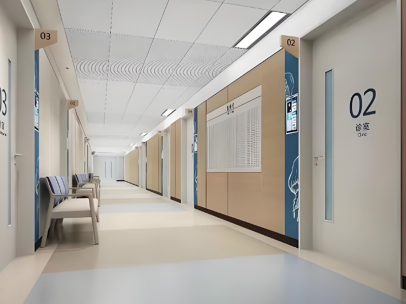
This makes them ideal for:
- Modern homes
- Offices
- Hotels
- Commercial spaces
Guangdong Leeyin Acoustics: Delivering High-End Acoustic Solutions
At Guangdong Leeyin Acoustics, we specialize in manufacturing premium wood slat wall panels and acoustic panels designed for global markets.
As a leading exporter in China’s wood slat acoustic panel industry, we are committed to delivering high-quality products that meet international standards.
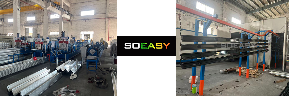
Our Advantages
- 20,000㎡ modern production facility
- Advanced automated manufacturing technology
- Strict quality management systems
- Strong large-scale production capacity
- Extensive global export experience
We focus on producing acoustic panels that offer:
- Reliable acoustic performance
- Superior craftsmanship
- Modern aesthetic design
- Long-lasting durability
Our products are widely used in residential, commercial, and hospitality projects worldwide.